Pneumatic chucks are mechanical devices used to clamp workpieces on machine tools. Manual chucks are more common, but with the development of technology, pneumatic chucks, hydraulic chucks and electric chucks have appeared. These chucks are also Have their own advantages and powerful.
How the pneumatic chuck works
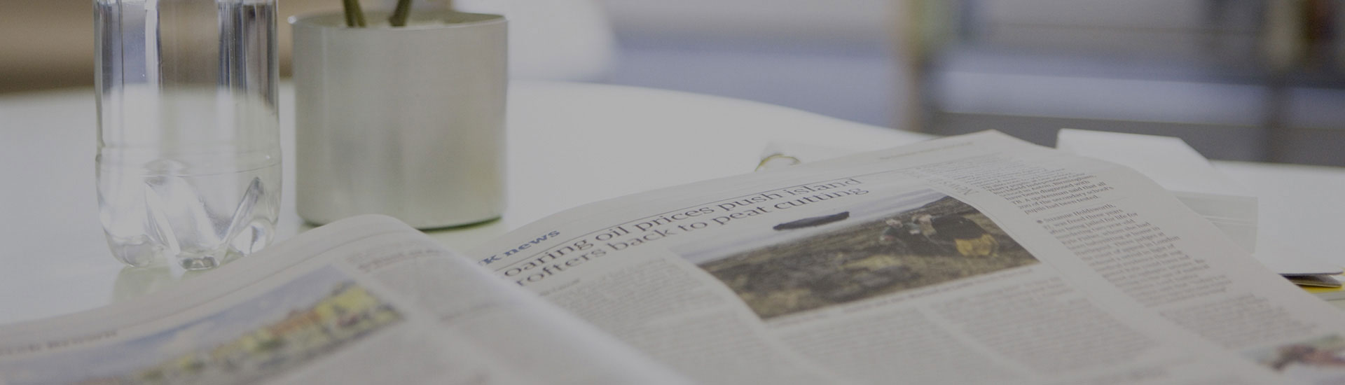
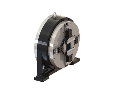
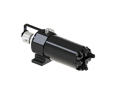
The main working accessories of the chuck: imported air pipe, gas distribution switch, exhaust port, air passage, air passage connector, rolling bearing, cylinder bearing, piston, tie rod, lathe spindle, short arm, claw, long arm.
The pneumatic chuck is called "claw". It is the main working part. There are many types of grippers. There are many from two claws to four claws. The power source of the gripper is from the cylinder, and the cylinder is used to compress the air. When the air is squeezed, it pushes the piston. Through the aggravation and release of the air, the pneumatic chuck is tightened to the release action. Repeatedly, the working state of the pneumatic chuck in our eyes appears.
1. Check if the chuck connecting flange is connected with the step opposite to the opposite side of the chuck;
2. Check whether the inner hole of the connecting sleeve matches the outer diameter of the spindle of the machine tool;
3. Clear the debris in the spindle hole;
4. Install the connecting sleeve on the outer diameter of the spindle at the end of the machine. Before and after tightening, use the table base and the dial indicator to correct it. The radial outer diameter and axial end face of the runout should be less than 0.03mm.
Pneumatic chuck installation steps
5. Wipe the chuck and the connecting flange cleanly, put the telescopic hose on the clamp and insert it into the two air source plugs on the reverse side of the chuck, and then clamp it with pliers (clamp the protruding part inwardly to clamp) That is, the pipe is smoothed out (the pipe does not have a bend phenomenon), and it can be entangled with tape;
6. Place the chuck with the air pipe inserted next to the machine connection flange (you can use a wooden board to raise it to the parallel with the flange), and then pull the pipe (through the spindle hole) to the tail of the shaft with the tow item. Pull the chuck to the connecting flange while pulling the pipe, and fasten the chuck to the flange through the connecting hole on the flange;
7. Pull the tube as far as possible (there is resistance on the hand and the tube is also straightened at this time). Wrap the tube around the spindle hole and insert it with a screwdriver or other object to prevent it. After the hand is released, the tube rebounds directly into the spindle hole, and then the excess tube is cut off at a distance of 100-150 mm from the orifice. The gas is blown into the two tubes to see which one is clamped. The action and the loosening action are marked with a marker on the pipe of the clamping action as No. 1, and the other is No. 2, and the mark can be made in advance when the gas pipe is pulled out;
8. Put the two air pipes on the clamps and insert them into the plug of the air pressure controller and clamp the clamps with pliers. When inserting, please recognize No. 1 to No. 1, and No. 2 to No. 2, then The item blocking the hole at the spindle is removed. At this time, the tube will be bounced into the hole of the spindle. Screw the left-hand nut on the air pressure controller to the connection sleeve, and use the iron or wire type traction device to press the air pressure controller. The anti-rotation bolt on the device is fixed on the machine body to prevent it from being rotated by the rotation of the main shaft;
9. Install the electric control board in the hidden position of the equipment (to prevent collision during operation), connect the power supply to AC220V, insert the connecting air pipe into each plug separately, the left end of the air pressure controller is No. 1, the middle is On the 2nd, the socket under the electric control board is No. 1, and the top is No. 2. Then remove the oil container next to the pressure gauge and add the clean No. 46 lubricant (8 points full), pull the total air intake. Insert into the left end socket of the electric control board (next to the pressure gauge), and then adjust the operating pressure according to the processing requirements;
10. When adjusting the pressure, lift the black knob above the pressure gauge upwards, clockwise to increase the pressure, and vice versa to lower the pressure. After the adjustment is completed, press the knob down to reset.